While designing road bridges and culverts, the following loads forces and stresses should be considered, where applicable:
1. Dead load
2. Live load
3. Snow load
4. Impact or dynamic effect due to vehicles
5. Impact due to floating bodies or vessels
6. Wind load
6. Longitudinal forces caused by the tractive effort of vehicles or by braking of
7. Longitudinal forces due to frictional resistance of expansion bearings.
8. Centrifugal forces due to curvature.
9. Horizontal forces due to water currents.
10. Buoyancy
11. Earth pressure, including live load surcharge,
12. Temperature effects
13. Deformation effects
14. Secondary effects
15. Erection stresses
16. Forces and effects due to earthquake
17. Grade effect (for the design of bearings for bridges built-in grade or cross fall)
18. Wave pressure.
The basic philosophy governing the design of bridges is that a structure should be designed to sustain with a defined probability all actions likely to occur within its intended life span.
In addition, the structure should maintain stability during unprecedented actions and should have adequate durability during its life span.
Typical combinations of loads and forces to be considered in the design and allowable increases in permissible stresses for certain combinations are given in the Code.
It will be necessary to ensure that when steel members are used, the Jud maximum stress under any combination does not exceed the yield strength of the steel.
Based 0gond on observations from recorded earthquakes, it is not considered probable that wind load and AA 28 earthquake will occur simultaneously.
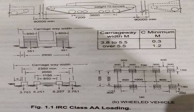
Describe the IRC Class AA loadings forces and indicate the conditions under which they should be used.
IRC Class AA Loading. This loading consists of either a tracked vehicle of 700 kN or a wheeled vehicle of 400 kN with dimensions as shown in Fig.
1.1. The tracked vehicle simulates a combat tank used by the army. The ground contact length of the track is 3.6 m and the nose to tail length of the vehicle is 7.2 m.
The nose-to-tail spacing between two successive vehicles shall not be less than 90 m. For two-lane bridges and culverts, one train of Class AA tracked or wheeled vehicles whichever creates severer conditions shall be considered for every two-lane width.
No other live load shall be considered on any part of the above two-lane carriageway when the Class AA train of vehicles is on the bridge.
The Class AA loading is to be adopted within specified municipal localities and along specified highways. Normally, structures on National Highways are provided for these loadings.
Structures designed for Class AA loading should also be checked for Class A loading, since under certain conditions, severe stresses may be obtained under Class A loading.
Give a critical review of IRC loading for Bridges.
Review of IRC Loadings Bridges
Thomas has reported a comparative study of the IRC loadings with the loadings of seven other countries.
He has shown that the IRC loading is the most severe for a single-lane bridge, but is less severe than the French, German, Japanese and British loadings for a two-lane bridge. Further, the loadings are complicated in application to design, especially if Class 70R, Class AA, and Class A loadings are to be considered in the design to determine the severest effects.
Very little information is available on the basis for the IRC loadings. While considerable refinement in the methods of analysis and design has been achieved, studies on the accuracy and adequacy of the assumptions of loadings have been neglected.
The laborious computations involved in applying the IRC loadings to an actual design may create an impression that the design moments are being assessed precisely.
In fact, the IRC loadings have little relation to the vehicles currently in use in the country.
The Class AA tracked vehicle load of 700 kN is by no means an accurate representation of present military tanks, and a specified tail-to-nose distance of 90 m is not likely to be observed in the event of any emergency.
Similarly, axle loads a spacing specified for wheel trains need not be exact.
While trucks manufactured in our county could perhaps be controlled, imported vehicles may not satisfy these specifications.
Thus the design moments and shears assessed from these hypothetical loadings after laborious computations can at best be only approximate.
The value of refinement of knowledge and accuracy of prediction of the behavior of structures under load is considerably diminished if it is not matched by corresponding precision of estimation and costing of the loadings that cause that behavior.
Even basic anomalies exist in the prescribed loadings. For example, the nose-to-tail spacing between two successive vehicles of Class AA tracked vehicle is 90 m while that for Class 70R is the 30 m, though the vehicles are very similar in both cases. Further, the justification for the use in India of severer loadings than in advanced countries deserves serious consideration.
In view of the above, the author strongly advocates the dropping of Class 70R loading and the development of simpler and more realistic loadings.
With a view to stimulating efforts towards the development of simplified standard loadings, it was proposed 1968 equivalent simplified loadings applicable for slab bridges up to 7.6 m.
The proposed loading consisted of a uniformly distributed load applied in conjunction with a knife-edge load.
The magnitudes were indicated for heavy loading, standard loading, and light loading, corresponding to IRC Class AA, Class A, and Class B loadings.
Thomas has subsequently evolved a new loading standard on similar lines but justified in greater detail and over a wider span range.
The basis for IRC provisions regarding impact is not clear. The actual impact factor will depend on the bridge span, the surface characteristics of the bridge, and the spring constant of the vehicle.
Systematic studies are needed to derive realistic impact factors for conditions in our country.
Field experiments in Britain by Mitchell indicated that the impact effort need not be considered for the full live load but need only be applied to the heaviest axle or the pair of adjacent wheels causing the maximum moment or shear.
Based on the above study, and practice in some other countries.
Thomas has advocated that the impact allowance be taken as 30 percent and that this allowance be applied only on the heaviest axle or the pair of adjacent wheels, which produces the greatest bending moment or shear as the case may be.
List the Indian Railway Standard design of Railway Bridges.
Indian Railway has been a pioneer in the construction of bridges. Currently, there are about 116000 bridges of all types and spans on the Indian Railways, making an average of two bridges per route km.
Nearly 20% of the bridges are girder bridges, while arch bridges account for about 19%, followed by slab culverts at 25% and others at 19%.
Railway bridges in India are to be built to conform to the Indian Railway Standards (IRS) laid down by the Ministry of Railways, Government of India, as below:
1. The loads to be considered in design are given in IRS Bridge Rules.
2. The details of the design of steel brides should conform to IRS Steel Bridge Code.
3. The details of the design of railway bridge members in plain reinforced concrete, and prestressed concrete should be in accordance with IRS Concrete Bridge Code.
4. Masonry and plain concrete arch bridges should be detailed so as to conform to the IRS Arch Bridge code.
5. The substructure for bridges should be in accordance with IRS Bridge Substructure Code.
Railway tracks are classified according to the width of the track (gauge) and according to the importance of the line.
What are the various components of concrete? What is the role of each component?
Components of Concrete
Cement concrete is produced by mixing cement, sand (fine aggregate), crushed stone (coarse aggregate), and water in suitable proportions. Approved admixtures may be added to enhance any desired property of the concrete.
Cement used for bridge construction is normally any one of the following : (a) Ordinary Portland le Cement (OPC), 33 grade, conforming to IS:269 (b) OPC, 43 grade, conforming to IS:8112 ; (c) OPC, 53 grade, conforming to IS:12269; and (d) Rapid Hardening Portland Cement in e accordance with IS:8041.
Cement conforming to IS:8112 and IS:12269 are nowadays used for structural concrete for bridges. The age of cement at the time of use should not be more than 90 days for reinforced concrete and not more than 60 days for prestressed concrete.
All coarse and fine aggregates shall conform to IS:383. Coarse aggregates shall consist of clean, hard, strong, dense, non-porous, and durable pieces of crushed stone, gravel, or shingle.
The maximum size of the coarse aggregate should be less than one-quarter of the minimum size of the member or 10 mm less than the minimum lateral clearance between individual reinforcement or 10 mm less than the minimum clear cover to any reinforcement.
The preferred nominal size of coarse aggregate is 20 mm for reinforced concrete and prestressed concrete. For plain concrete, the preferred nominal size may vary from 20 mm to 40 mm. Fine aggregates shall consist of hard, strong, durable, clean pieces of natural sand, crushed stone, or gravel to size passing 4.75 mm sieve.
Grading of aggregates shall be such as to produce a dense concrete of the specified strength with adequate workability, to enable placement in position without segregation and without the use of excessive water content.
Water used for mixing and curing shall be clean and free from materials harmful to concrete or reinforcement.
Potable water is generally considered satisfactory for mixing concrete. As per IRC:21, solids in water should not exceed the limits as below: organic 200 mg/lit, inorganic 3000 mg/l, sulfates 500 mg/l, chlorides 200 mg/l, and suspended matter 2000 mg/.
The pH value shall not be less than 6. Curing of concrete by water prevents drying up of the intrinsic moisture inside the capillaries of the concrete and thus aids hydration of cement (to gain strength) and reduce shrinkage cracking.
Admixtures are available for increasing the workability of concrete (plasticizers) facilitating the reduction of water-cement ratio and for retardation of the setting of cement during hot weather concreting.
Concrete properties such as durability, strength, and service life can be enhanced by the use of suitable mineral and chemical admixtures.
What do you mean by Ready Mix Concrete (RMC)? What are the advantages of RMC?
Ready-mixed concrete
At many bridge sites, especially in urban areas, preparation of concrete at the construction site becomes difficult due to the non-availability of adequate space for storage and handling of the constituent materials and for mixing operations.
When the construction activities in a city are of Such magnitude as to assure a sustained demand for a large volume of concrete, it is desirable to establish ready mixed concrete (RMC) plants in the outskirts of the city and to transport the concrete in special transit mixer trucks to the construction site at the right time.
Though the use of RMC is not yet widespread in many Indian cities, this development is inevitable in the near future,
A typical RMC plant has the following components
1. Central batching plant with a capacity of 30 to 200m of concrete per hour; one
2. Transit mixer trucks to transport concrete to construction sites with the help of rotating type transit mixers of capacity about 6 m; and
3. Concrete pumps and conveyors to deliver concrete at the work sites.
The use of ready mixed concrete has several advantages. Firstly, the quality of the concrete is to assure with a lower standard deviation for the compressive strength.
The automatic batching plant can be of state-of-the-art technology.
All the operations are carried out under strictly controlled conditions, as there is usually a quality control laboratory attached to the plant.
Concrete grade and cement type could be specified. Secondly, the construction contractor is relieved of the inconvenience of procuring different materials at the required time.
Thirdly, stockpiling of huge quantities of materials like aggregates and cement at the construction site is eliminated, resulting in cleaner and less polluted surroundings at the worksite.
Fourthly, the use of RMC facilitates speedy construction through continuous mechanical operations including placement of concrete by pumping.
Fifthly, the concreting operations can be managed with much less labour force, which also results in avoidance of unauthorized hutment colonies around the worksite.
How Bridge Balance Forces? | Different Type of Forces on Bridge
State the usual types of Reinforced Concrete Bridges and Indicate the Span Range in which each type would be applicable.
Reinforced concrete is well suited for the construction of highway bridges in the small and medium span range. The usual types of reinforced concrete bridges are:
Slab bridges;
Girder and slab (T-beam) bridges;
Hollow girder bridges;
Balanced cantilever bridges;
Arch bridges; and
Bowstring girder bridges.
For slab bridges of spans longer than 10 m, the dead load can be reduced by adopting voided slab design using circular polystyrene void formers.
In this case, it is important to ensure that the void formers and the reinforcement are held firmly in the formwork during construction.
The void 14br diameter is usually less than 0.6 of the slab thickness.
In order to cater to shear stresses, the voids have stopped some distance away from the supports to leave a solid section at the support Typical T-beam bridge of 14.5 m effective span, is the most frequently used type.
The Ministry Road Transport & Highways, Government of India (also referred to as MORTH) has specified that for bridges on National Highways with a total length less than 30m the overall width between the outermost faces of the railing kerb is adopted the same as the roadway width of the adjoining road, i.e, at 12.0 m for two-lane carriageway plus shoulders carriageway of 7.5 m with kerbs of 600 mm on either side, giving a total width of the bridge of 8.7 m. Such a width will be applicable for State Highways and also for NH in rural sections for a T-bearn bridge of multiple spans resulting in a total length in excess of 30 m. The procedure used therein could be adapted for other types with suitable modifications.
The total cost is usually the governing factor in the selection of the proper type of concrete bridge in any particular case.
However, the problem is sometimes complicated by special requirements, such as aesthetics, navigational or traffic clearance below the bridge, limited time for construction, and restrictions on the provision of formwork.
Also, Read This