Types of mivan drawing
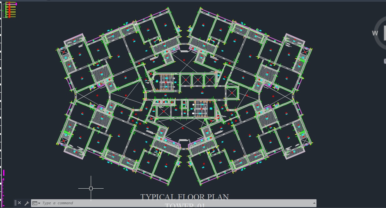
1) floor plan
2) center line
3) section drawing
4) elevation drawing
5) working drawing
6) 3D design
7) shell plan
8) shear wall layout
9) IC LAYOUT
10) WALL LAYOUT PANEL PLAN SECTION ELEVATION
11) SL LAYOUT
12) DECK LAYOUT
13) BEAM BOTTOM LAYOUT PLAN
14) KIKER LAYOUT
15) CHAJJA TOP / SUNK LAYOUT
16) UPSTAND LAYOUT
17) RELARJ
18) SOLJAR
19) CC PLAN
20) ECA PLAN VERTICAL EXTERNAL CORNER ANGLE FOR START BOTTOM WITHOUT RK
21) BC PLAN INTERNAL BEAM CORNER
22) PC PLAN PLATE COVER WINDOW SEAL 700 PC 280
23) LS PLAN
24) SX PLAN OPEN PART
Your Guide to Mivan Drawings: Blueprints for Modern Construction
Hey there! If you’ve ever looked up at a sleek new apartment building or a shiny office complex and wondered, “How do they build something so massive, so fast, and so precise?” you’re in the right place. Chances are, they’re using the Mivan construction technique, and the secret to getting it right lies in a special set of types of Mivan drawings. Think of these drawings as the ultimate instruction manual for building with giant aluminum molds. They’re not just sketches; they’re detailed, coordinated plans that ensure every wall, window, and beam fits together perfectly. Whether you’re a student, a new site engineer, or just curious about how modern buildings rise from the ground, this guide will walk you through the essential drawings you need to know, in plain, conversational language.
What is Mivan Construction, Anyway? A Quick Primer
Before we dive into the drawings, let’s get on the same page about what Mivan actually is. Originating in Europe and now a global phenomenon, Mivan is a revolutionary aluminum formwork system. Instead of traditional timber or steel forms, it uses lightweight, pre engineered aluminum panels to cast entire sections of a building walls and slabs in one continuous concrete pour.
The result? Incredibly fast construction cycles, superb quality finishes (often requiring little to no plaster), and exceptional strength. But here’s the catch: this speed and precision are 100% dependent on meticulous planning. And that planning happens entirely on the drawing board (or these days, on computer screens). Mivan shuttering drawings are the non negotiable foundation of the entire process.
The Master Key: The Mivan Panel Layout Drawing (The “Big Picture”)
Imagine trying to solve a giant, three dimensional puzzle. That’s what building with Mivan is like, and the Mivan Panel Layout Drawing is your puzzle box lid it shows you the complete picture.
What It Is & Why It’s The Most Important Drawing
The cornerstone of the entire set. It’s a floor-by-floor plan that shows exactly where every single aluminum panel will be placed. Created by specialist Mivan consultants or very experienced structural engineers, this drawing transforms architectural plans into a practical assembly guide for the formwork.
Key Details You’ll Find on This Layout:
- Panel Marking & Numbering: Every panel has a unique ID (like W01 for Wall Panel 1, S45 for Slab Panel 45). This is the language the site team uses.
- Panel Sizes & Types: It specifies the standard sizes (e.g., 300mm, 600mm wide panels) and special types for corners, beam sides, or rockers (panels with a kick).
- Alignment & Joints: It clearly marks how panels align with each other and with structural elements, ensuring there are no gaps or misalignments during the concrete pour.
My Two Cents: I remember walking a new engineer through his first Mivan site. He was overwhelmed until we pulled out the Panel Layout. Suddenly, the chaos of aluminum on the ground made perfect sense. “So that’s how this wall connects to that beam!” he said. This drawing turns confusion into clarity.
Breaking Down the Blueprint: Essential Types of Mivan Drawings
Now, let’s get into the specifics. The Panel Layout is just the start. A full set of Mivan formwork drawings is a family of documents, each with a critical role.
1. Mivan Wall Panel Drawings
These are the vertical plans. They provide an elevated view of each wall section, showing:
- Panel Configuration: Exactly which standard and special panels make up a wall.
- Tie Hole Locations: The precise spots for through-ties (the metal rods that hold two opposing panels together against concrete pressure). Getting this wrong can lead to leaks or bulges.
- Interface Details: How the wall formwork meets the slab or beam formwork above and below.
2. Mivan Slab/Deck Panel Drawings
This is the “ceiling” plan for the floor below. It details the arrangement of deck panels that support the concrete slab. Key features include:
- Decking Layout: Placement of horizontal panels and deck props (the adjustable legs that hold everything up).
- Drop Beam Details: Sections showing how formwork is configured for beams that are “dropped” below the slab level.
- Prop Sequencing: Sometimes included, this shows the order for removing props after the concrete has gained strength.
3. Mivan Component & Assembly Drawings
Think of these as the IKEA instructions for the formwork itself. They zoom in on the connections.
- Joint Details: How panels clip together using pins, wedges, and clamps.
- Supporting System Details: How soldiers (vertical supports), walers (horizontal beams), and through-ties are assembled.
- Special Element Drawings : For tricky areas like architectural features, balcony openings, or staircases. Stairs, in particular, require very detailed Mivan formwork drawings for stairs, showing the intricate arrangement of riser and tread panels.
4. Mivan Reinforcement Drawings
While not always part of the formwork supplier’s package, these are inseparable in practice. They show the placement of steel rebar within the Mivan molds. The Mivan shuttering drawings and reinforcement drawings must be perfectly coordinated to avoid clashes between rebar and tie holes.
Why Getting These Drawings Right Is a Game-Changer
Using accurate, clash-free Mivan aluminium formwork drawings isn’t just a good idea it’s what makes the system viable.
- Speed: On site, workers assemble the puzzle from a clear guide. No guesswork means no delays.
- Cost Savings: Prevents costly on-the fly modifications, material waste, and rework.
- Safety & Quality: Properly detailed connections and supports ensure a rigid formwork that minimizes the risk of accidents or poor-quality concrete finishes (like honeycombing).
FAQs: Your Mivan Drawing Questions, Answered
Q1: I’m a beginner. Which drawing should I study first?
A: Start with the Mivan Panel Layout Drawing. Spend time understanding the numbering system and how it correlates to the physical panels on-site. It’s the map that makes all the other drawings make sense.
Q2: Who typically prepares these Mivan drawings?
A: They are usually prepared by the Mivan formwork supplier or a specialized detailing consultancy with proven expertise in aluminum formwork systems. The structural consultant of the project then reviews and approves them to ensure integrity.
Q3: What’s the biggest common mistake in these drawings?
A: A lack of coordination. The most frequent issue is a clash between the Mivan formwork drawings and the structural/architectural services (like duct openings or electrical conduits). This is why modern projects use BIM (Building Information Modeling) to identify and resolve these clashes in 3D before a single panel is ordered.
Q4: Are these drawings different for every project?
A: Absolutely. While panels are standardized, every building’s geometry is unique. The drawings are fully customized for each project’s architectural and structural design, which is why they are so critical.