A typical water connection, connecting the service pipe with the municipal water mains is as shown
The water connection consists of 1) Ferrule, 2) a goose neck, 3) a service pipe, 4)a stop cock, and 5) a water meter.
1. Ferrule a ferrule is a right-angled sleeve made of brass or gunmetal and is joined to a hole drilled in the water mains, to which it is screwed down with a plug.
Its size usually varies between 10 to 50 mm in diameter. For all other connections of more than 50mm a tee branch connection, off the water mains, is used.
2. Goose neck: Gooseneck is a small-sized curved pipe made of a flexible material ( usually lead) and is about 75 cm in length forming a flexible connection between the water mains and the service pipe.

3. Service pipe: A service pipe is a galvanized iron pipe of less than 50mm diameter. It should be laid underground in a trench in which no sewer or drainage pipe is laid. The service pipe which supplies water to the building through the municipal main is thus connected to the main through the goose neck and ferrule.
4. Stop cock: The stop cock is provided before the water enters the water meter in the house. It is housed in a suitable masonry chamber with a removable cover and is fixed in the street close to the boundary wall in an accessible position.
Sometimes it is provided just before the water meter inside the house, keeping both of them in one chamber.
5. Water meter: It measures and records the quantity of water consumed in the house. The domestic type water meter generally employed for houses is fitted into the service pipe with unions, which enables the meter to be changed where necessary.
The meter is fixed in an iron box fitted in an opening or cavity made in the boundary wall of the house and is covered with a movable iron cover.
How municipal water mains are connected to private buildings and houses for giving water supply connections
Discuss RCC pipes and their advantages and disadvantages
RCC pipes are generally made from 1:2:2 cement concrete with a maximum size of aggregates as 6 mm. They are provided with circumferential reinforcement to carry hoop tension and a nominal longitudinal reinforcement equal to 0.25% of the gross cross-sectional area of concrete.
Their thickness varies from 2.5cm to 6.5 cm for pipes of diameters varying from 0.1m to 1.2m.
These pipes are joined by placing the protruding end bars of different lengths butting against one another and welding them and finally filling the gap with rich cement concrete so as to provide a watertight joint
RCC pipes Advantages are:
1. They can resist external compressive loads and do not collapse under nominal vacuums and traffic loads.
2. They are not corroded by normal potable water and soils.
3. They are quite strong and their useful life is 75 years or so.
4. They are easy to construct either at the site or at factories and with local ingredients.
5. The coefficient of expansion being low, expansion joints may not be needed when laid above the ground
6. If laid underwater the empty pipes do not float because of their heavy weight.
RCC pipes Disadvantages are:
1. alkalis or sulphur compounds.
They are likely to corrode by ground waters due to the presence of acids,
2. They are difficult to be repaired
3. They cannot withstand very high pressures.
4. They are heavy and bulky, and hence difficult to transport.
5 Making of connections in them is a little difficult job
6. They tend to leak due to shrinkage cracks and porosity.
Discuss the advantages and disadvantages of asbestos pipes.
Advantages of asbestos pipes:
1. They are light and hence easy to transport
2. They can be easily assembled without skilled labour
3. They are highly flexible and may permit as much as 12-degree deflection in laying them around curves
4. Expansion joints are not required as the coefficient of expansion is low and the joints are also flexible
5. They are very smooth and are hydraulically efficient pipes. Their carrying capacity do not reduce with time
6. They are suitable for small-size distribution pipes.
Disadvantages of asbestos pipes:
1. They are costly
2. These pipes do not have much strength and are brittle and soft. They are liable to get damaged by excavating tools or during transportation transit.
3. The rubber joint seal may deteriorate if exposed to gasoline or other petroleum products, and hence cannot be used for transporting petroleum products.
What are the different types of distribution reservoirs?
The following types of reservoirs are:
1. Earth reservoirs
2. Masonry and RCC reservoirs
3. Elevated reservoirs
a. Standpipes
b. Elevated tanks
1. Earth reservoirs: These reservoirs are used when a large quantity of water is ti be stored before the treatment. These are constructed by excavating to the required depth below the ground surface and the excavated earth is used for the embankment construction to the required height above the ground.
A core wall may be constructed to make the earthen reservoir impermeable. The embankment should be keyed down to the bottom. Outlet pipes may be provided in the embankment walls at various places to minimize the seepage of water.
To prevent the loss of water and leakage, the sides and the bottom of the reservoirs should be properly lined with bricks, stones, asphalts or cement concrete, etc.
2. Masonry or RCC underground) reservoir: These are constructed on high natural grounds. It is made of bricks, stones, plain or RCC. While designing a groundwater table is kept in mind and the side walls should be able to take up the pressure of water when the reservoir is full, and the earth’s pressure when it is empty.
The floors are constructed with RCC slab and bituminous compounds may be used at all construction joints for water tightness.
3. Elevated Reservoirs: Generally two types of elevated reservoirs are used
a. Standpipe: These are generally made of RCC or steel and are circular in plan. These are up to 12m in height. If it is possible to locate the stand-pipe on a hill or high ground then its entire capacity can be made use of successfully.
Its main function is to increase pressure on the distribution system by creating extra storage in the tank above the elevation required to give the necessary pressure for distribution.
These are provided with single inlet and outlet pipes terminating at the lower elevation of the useful capacity of the tank, scour or drain pipe to drain out and flush the tank, and the overflow pipe to discharge surplus water.
b. Elevated tanks: These are popular because they have a long life, require very little maintenance, and give a good appearance in the locality. The tank is provided with an inlet, outlet, overflow, and scour or drain pipes.
A depth level indicator with a float arrangement is provided to measure the depth of the water in the tank. About 60 to 100 cm balcony is provided around the tank for inspection and maintenance of the tank and a step-iron steel ladder are also fixed in the inner walls of the tank.
The tank is covered and is provided with a manhole and ventilating pipe and lightning conductors. These are used to store a large quantity of water.
Discuss how the storage capacity of a distribution reservoir is determined by mass curve method
The storage capacity of the reservoir is determined by the principle of the mass diagram. A mass curve showing the rate of demand is drawn with time as abscissa and the total flow of demand during the period as ordinate.
This is represented by line P. if the ends of the line Pare are joined by a straight line marked Q, then line Q represents the mass diagram of pumping into the tank and its slope represents the rate of pumping.
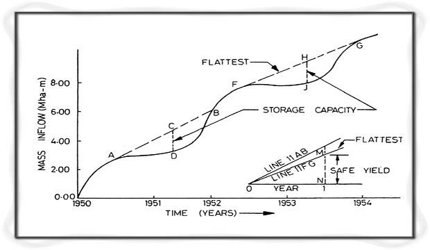
From the graph, it may be observed that the tank is full at the point a and empty at the point b, so that its tangents are drawn at points a and b parallel to the line Q, the vertical intercept bc on the scale would represent the required capacity of storage of the balancing tank.