Types of joints used in bridges ? What is joint?
The joint is the weakest and most vulnerable area in bridge design. Unless properly designed, the distress at the joints bridge will lead to many maintenance problems, ranging from the spelling of concrete edges at the joint to the deterioration of pier caps.
With the extremely high density of traffic occurring on most major bridges maintenance work on the bridge should be restricted to a minimum length of time.
Hence the joints on a bridge should be so designed as to perform satisfactorily for a long time without requiring repair or replacement.
Why Joints are Provided in Road Bridges?
Three types of joints bridge structure (a) construction joint, (b) expansion joint, and (c) contraction joint. Construction joint is necessary whenever the placement of concrete has to be stopped temporarily before the completion of the entire monolithic portion under construction.
Such temporary suspension of concrete placement may sometimes be unexpected, if it is due to failure of machinery such as concrete mixer, vibrator, etc.
But often, it may be scheduled to facilitate the addition of reinforcements for a top portion, as in the case of the stem of a retaining wall.
When foundations of adjacent parts of the structure are at different levels, as in the case of the junction between the abutment and the wing wall, a construction joint should be provided.
Construction joints should be positioned to minimize the effects of discontinuity on the durability, structural integrity, and appearance of the structure.
Joints should be located away from regions of maximum stress caused by loading, particularly where shear and bond stresses are high.
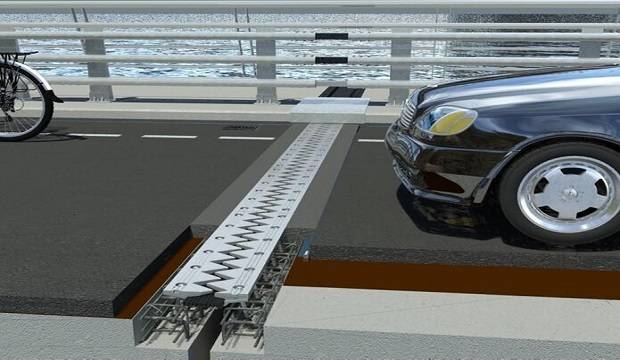
Expansion joints and contraction joints are provided to take care of deformations due to changes in temperature.
The difference between the two types is in the depth of the joint and also in the width.
Contraction joints, where provided, will be only for a part of the depth of the slab and will often be of smaller width. Expansion joints will be the full depth of the member.
State the performance criteria for an effective joint sealing system bridge.
An effective joint sealing system bridge for a long span bridge must satisfy the following performance criteria”.
1. It must have the capability to successfully respond to any combination of the many types of movement that might occur on a particular bridge, e.g. straight distance change between the joint interfaces, racking distortion from the many variations of skews, horizontal, angular, vertical and articulation motion patterns, differential vibration of slab ends, impact, and warping.
2. It must seal out the entry of all foreign material with a potential for producing restraint. It should guarantee that bearing seats, pier caps, and bends do hot receive accumulations of these materials along with chemicals deleterious to the performance life of steel or concrete.
3. It must seal out the entry of free water.
4. It must be capable of absorbing the various types and ranges of movement within itself without being extruded above or expelled from the joint opening.
5. with respect to the riding surface of the sealing system, it must be constructed of materials which have the capability to withstand were and impact from repetitive and heavy traffic loading besides durability against petroleum products and weather.
6. it should have a long service life, ideally equal to the life of the bridge short-lived sealing solution should have provision for simple and easy replacement with minimum cost.
Under what condition elastomeric bearing is provided? Explain in details its components & salient features.
GENERAL:
Since metallic bearings are expensive in first cost and maintenance, the recent trend is to favour elastomeric bearings“.
An elastomeric bearing accommodates both rotation and translation through deformation of the elastomeric.
These bearings are easy to install, low in the first cost, and require practically no maintenance.
They do not freeze, corrode or deteriorate. Barring an earthquake, the only probable causes for failure of an elastomeric bearing are inferior materials, incorrect design or improper installation.
Elastomeric bearings are ‘forgiving’ in that they can tolerate loads and movements exceeding the design values.
Further, elastomeric bearings need no positive fixing like metallic bearings. The height of is minimum and much less than roller or rocker bearings, thus contributing to a reduction in the cost of approaches.
Removal and replacement, if necessary. can be achieved easily.
Since replacement of bearings during the service life of the bridge may become necessary, the bridge design should provide for suitable recesses to insert jack for lifting the deck along with the necessary additional local strengthening in the superstructure.
An elastomer is any member of a class of polymeric substances obtained after vulcanization and possessing characteristics similar to rubber, especially the ability to regain shape almost completely after large deformation.
Out of the many forms of synthetic rubbers available, polychloroprene rubber known as ‘neoprene’ is the best known and best tested in use. The natural rubber has many shortcomings.
It has only moderate weathering resistance, is inflammable, and is vulnerable to attacks by oxygen, ozone, oil, and fuels.
The elastomer has better weathering resistance and is flame resistant. By adding antioxidants and antiozonants, its resistance to attack by oxygen and ozone can be increased.
Natural rubber bearings are not permitted. The only elastomer is allowed for use in bridge bearings.
Explain the process of installing Elastomeric Pad Bearings.
For in-situ construction, the bearing pad should be placed at the correct location With proper alignment.
The bearing should be protected to avoid grout or concrete encasing or damaging the sides of the bearing.
This can be achieved by surrounding the bearing with expanded polystyrene and taping adequately between the top surface of the bearing and the polystyrene.
After the structure has been cast, the polystyrene should be carefully removed.
When precast concrete girders are seated on the pad bearings, the bearings should be first placed at the correct location with proper alignment.
The lowering of the precast girdes and seating should be done gradually without any jerk.
Movement of the bearing during the seating of the girder should be carefully prevented.
This can be done by using epoxy-based resin bedding mortar below the bearing to provide a sufficient bond between the bearing and the above the bearing prior pedestal.
In addition, a skim coating layer of mortar can be placed to beam seating to allow for minor irregularities between the two surfaces.
Though the design permits the bearing to be placed without any mortar, it will be prudent to apply the epoxy mortar as above.
All bearings installed along a single line of support should be of identical dimensions.
The author has come across situations where the construction inspectors have shown alarm even with moderate bulging of the elastomer between steel plates of the pad bearing.
Such moderate bulging is to be expected and allowed. The bulging becomes unacceptable if it is excessive, uneven among layers, and accompanied by cracks of the elastomer.
How would you provide kerbs for a submersible bridge?
In the case of submersible bridges, handrails, if provided, should be collapsible during floods, so as to minimize obstruction to the flow of water and passage of floating debris. It is, however, preferable to provide perforated kerbs along with diamond-shaped guideposts as shown in Fig. 4.1.
Describe the provisions of guide bunds for a major river at a bridge site.
In the case of major bridges across wide rivers, river training works such as guide bunds, spurs, and approach road protection works may sometimes be required.
Guide bunds are provided to channel the flow of floodwaters in the river towards the vent way of the bridge and to afford protection to the road embankment from flange attacks during floods.
Spurs are provided for training the river along the desired course by attracting, deflecting or repelling the flow of a channel.
Approach embankments may require the protection of slopes by pitching along the slopes and a short apron at the bed level.
Detailed guidelines for the design and construction of river training works are available in IRC 89.
Guide bunds can be straight or elliptical with a circular head and tail. Typical details of an elliptical bund are shown in Fig. 4.2.
Elliptical bund results in a more uniform flow through the bridge as compared to straight guide bund. The ratio of the major to minor axis is generally kept between 2.0 and 3.5.
The length of the guide bund is usually 1.0 to 1.25 L on the upstream side and about 0.2 L on the downstream side, where L is the length of the bridge.
The pitching on the riverside should be made with stones having a minimum weight of 04 kN. The thickness of pitching is computed from Equation t=0.06Q0.33
The thickness of stone pitching computed as above is checked to be between 0,3 m and 1.0 m.
A filter is provided under the slope pitching to prevent the escape of embankment material through the voids in the pitching.
An apm (known as a launching apron) is provided at the toe of the riverside slope for the protection of the toe.
The size of the stone should be such as to resist the mean design velocity as given by Equation.
d = 0.042 v2
where d = diameter of stone in
v = mean design velocity in m/s.
Fig. 4.2 Details of Guide Bund.
The minimum weight of stone used for the apron is 09.4 kN. The width of the launching apron is generally taken as 1.5 d, where d is the maximum anticipated scour depth below the bed level. The thickness of the apron is kept at 1.5 at the inner end and at 2,25 t at the outer end, as shown in Fig. 4.2.
What is the purpose of providing wearing course over concrete bridge deck? Explain along with its different types.
A wearing course (sometimes referred as wearing a coat) is provided over concrete bridge decks to protect the structural concrete from the direct wearing effects of traffic and also to provide the cross camber required for surface drainage. The wearing course may be of asphaltic concrete or cement concrete.
Asphaltic concrete wearing course is currently the preferred option as this permits the use of buried expansion joint for short spans facilitating a smooth transition between the bridge and the approaches for the riding surface.
The thickness of the wearing course is kept uniform and the top of the deck slab is adjusted to facilitate the cross camber for. surface drainage.
1. Asphaltic Concrete Wearing Course
The asphaltic wearing course of 56 mm uniform thickness is desirable when the road payment on the approach on either side of the bridge is of asphaltic concrete.
The wearing course consists of the following : (i) A coat of mastic asphalt 6 mm thick with a prime coat over the deck slab; and (ii) 50 mm thick asphaltic concrete wearing course in two layers of 25 mm each.
2. Cement Concrete Wearing Course
Cement concrete wearing a course of 75 mm uniform thickness in M30 concrete over concrete deck slab may be adopted in case of isolated bridges where the use of asphaltic concrete is inconvenient.
The wearing course should be reinforced with 5 6 200 in both directions where the deck slab is in compression and with 6 4 100 in both directions where the deck slab is in reinforcement at panel joints should be bent down to protect the ends of the joints.
The cement concrete wearing course should be laid in two longitudinal strips with the casting of alternate panels of equal length in each strip.
The joints of the panels in the two strips shall be staggered. While concreting the left-out panels, bituminous papers will be placed at the joints with the previously placed panels in order to get a separation between the panels.
Shuttering will have to be provided at the free ends for ensuring vertical face and also to attain good compaction.
Discuss how the construction method affects the total cost of a bridge.
The final cost of a bridge is the sum of the cost of permanent materials, the proportionate cost to the project of plant and temporary works, and the cost of labour.
The cost of permanent materials can be estimated reasonably correctly. With experience, a bridge contractor can deal competently with the cost of plant and temporary works.
But the labour cost does not lend itself to exact analysis. Recent competitive designs have attempted to introduce innovations in construction methods with a view to affecting the economy in the cost on labour by reducing temporary works and by minimizing the duration of site work.
The suitable techniques of construction of bridge superstructure will vary from site to site and will depend on the spans and length of the bridge, type of the bridge, materials for short spans up to 40 m, if the river bed is dry for a considerable portion of the year, whereas free cantilever construction with prestressed concrete decking would be appropriate for long spans in rivers with navigational requirements.
The current trend is towards the avoidance of staging as much as possible and to use of precast or prefabricated components to the maximum extent.
Also, construction machinery such as cranes and launching girders are coming into wider use.
In the case of bridges across wide rivers, considerably saving in construction cost has been achieved by innovative use of barge-mounted cranes for the erection of öne span at a time, as in the Delhi Noida bridge, and by adopting the incremental push launching method as in Yamuna bridge for Delhi Metro.
There are greater savings to be effected by paying attention to the method of construction even from the design stage than by attacking permanent materials.
Also, read that.