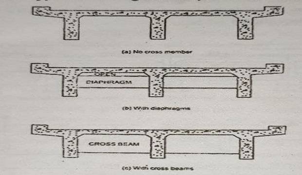
The types bridge superstructure may be arranged to conform to one of the following three types.
1. Girder and slab type, in which the deck slab is supported on and cast monolithically with the longitudinal girders. No cross beams are provided. In this case, the deck slab is designed as a one-way slab spanning between the longitudinal girders.
The system does not possess much torsional rigidity and the longitudinal girders can spread laterally at the bottom level. This type is not adopted in recent designs.
2. Girder, slab, and diaphragm type, wherein the slab is supported on and cast monolithically with the longitudinal girders.
Diaphragms connecting the longitudinal girders are provided at the support locations and at one or more intermediate locations within the span.
But the diaphragms do not extend up to the deck slab and hence the deck slab behaves as a one-way slab spanning between the longitudinal girders.
This type of superstructure possesses a greater torsional rigidity than the girder and slab type.
3. Girder, slab ad crossbeam type, in which the system has at least three cross beams extending up to and cast monolithically with the deck slab.
The panels of the floor slab are supported along the four edges by the longitudinal and cross beams.
What are the various components of the T-Beam Bridge?
Components of a T-Beam Bridge
The T-beam superstructure consists of the following components as also indicated in Fig. 1.3.
1. Deck slab
2. Cantilever portion
3. Footpaths; if provided, kerbs and handrails
4. Longitudinal girders, considered in the design to be of T-section
5. Cross beams or diaphragms
6. Wearing course.

Fig. 1.3. Components of T-beam Bridge with typical Dimensions for 20 m Clear Span.
Standard details are used for kerbs and handrails. The width of the kerb may vary from 475 mm to 600 mm.
Wearing course can be of asphaltic concrete of average thickness 56 mm or of cement concrete of M30 grade for an average thickness of 75 mm.
Footpaths of about 1.5 m width are to be provided on either side for bridges located in municipal areas; these may be omitted for bridges on rural stretches of roads. It is, however, desirable to provide footpaths even for a bridge on a rural section, if the overall length of the bridge is large.
Discuss in Detail the balanced cantilever bridges.
Balanced Cantilever Bridges:
If continuous spans are used, the governing bending moments can be minimized and hence the individual span lengths can be increased. But unyielding supports are required for continuous construction.
If supports settle, the net moments get modified in magnitude as well as in sense, resulting in distress to the structure.
Hence for medium spans in the range of about 35 to 60 m, a combination of supported spans, cantilevers, and suspended spans may be adopted as shown schematically in Fig. 1.4.
The bridge with this type of superstructure is known as a balanced cantilever bridge.
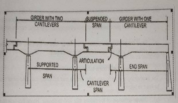
The connection between the suspended span and the edge of the cantilever is called as articulation.
The bearings at articulations should be alternatively of fixed and expansion types and can be in the form of sliding plates, roller-rocker arrangement, or elastomeric pads.
Elastomeric bearings form the preferred option in recent constructions.
The expansion joint should be filled with mastic filling at the wearing course level, though the other parts can be left open. Defects at articulations have been reported in many of the balanced cantilever bridges so far built in India.
The articulations should be competently designed, properly built, frequently inspected, and carefully maintained.
The cantilever span is usually about 0.20 to 0.25 of the supported span. The suspended span is designed as a simply supported span with supports at the articulations.
The reinforcements at the ends of the suspended span should be carefully detailed so as to carry the shear safely.
For the design of the main span, the maximum negative moment at the support would occur when the cantilever and suspended spans are subjected to full live load with no live load on the main span.
The maximum positive moment at the midspan would occur with a full live load on the main span and no live load on the cantilever or suspended span.
Similarly, the governing shears at the different sections are computed using influence lines. The bearings at the piers will be alternate of fixed and expansion types.
The cross-section of a balanced cantilever bridge can be of T-beam or hollow girder type.
Since the negative moments are usually larger in magnitude than the positive moment at midspan, the depth at support will be greater than at midspan.
The soffit can be arranged to be on a parabolic profile or as two inclined lines with a central horizontal line.
What are the advantages & disadvantages of Continuous girder bridges over simply supported bridges?
Continuous girder bridges have the following advantages over simply supported girder bridges:
1. The depth of decking at midspan will be much smaller. This is particularly important in the case of over bridges where the headroom available is generally restricted.
2. As a corollary to the above, the quantities of steel and concrete will be less, resulting in reduced cost. Also, reduced depth of deck leads to a decrease in the cost of approach ramps and earthwork.
3. Fewer bearings are required. At each pier, only one bearing is needed, as against two bearings required for simply supported designs. Hence the piers can be narrower. Although the cost of individual bearings will be higher, the total cost on bearings will be lower.
4. Fewer expansion joints will be required. For a continuOus girder design, only two ions are needed at the ends, while the simply supported girder design will require one joint o are abutment and pier. Elimination of joints enhances the riding quality over the bridge.
5. Since the bearings are placed on the center lines of the piers, the reactions of the continuous girder are transmitted centrally to the piers.
6. The continuous girder bridge suffers less vibration and deflection.
The disadvantages of continuous girder designs over the simply supported girder designs may be listed as below:
Uneven settlement of foundations may lead to disaster. Hence this type of structure should not be used in situations where unyielding foundations cannot be obtained at a reasonable cost.
The detailing and placing of reinforcements need extra care.
The sequence of placing concrete and the sequence of removing formwork has to be carefully planned.
Being statically indeterminate, the design is more complicated than simple beams.
Give the design consideration of Arch Bridges.
The arch axis is generally governed by three considerations: (a) span and rise from the road gradient and navigation or traffic clearances below, (b) the economical shape from point of view of saving of materials, and (c) the beauty of the intrados.
The most important parameter is the rise-span ratio, the economical value of which lies between 0.30 and 0.20. A large rise reduces the thrust and leads to a thinner arch section.
Flatter arches lead to more aesthetic structures. The usual profiles adopted in practice are parabolic, segmental, and elliptical. Parabolic arches will be admirably suited in rugged country with exposed solid rock for abutments. In plains, and particularly for a spandrel-filled arch, a segmental profile may be more satisfactory.
The elliptical shape is not much favored, except in cases where clearance requirements need an almost vertical surface of the soffit near the springing.
A parabolic profile is first assumed and the thrust fines are drawn for the dead load and for dead load plus live load.
The final profile is adjusted to result in minimum flexural stresses in the arch section.
Arches are designed by trial and error. First, the preliminary dimensions are assumed. For solid ribbed arches, the span-depth ratio is generally in the range of 70 to 80. Influence lines for horizontal thrust and bending moments are constructed using first principles.
The resulting stresses are then checked against allowable stresses, and the sections are redesigned, if necessary.
For arches of large spans, the arch cross-section is typical of box type with two or three cells.
The arch width and depth are chosen from stability considerations. For ease in construction, the outer dimensions of the arch cross-section are kept constant. The diaphragms under the spandrel columns are kept vertical.
Types of Bridges Based on Superstructure.
Discuss the construction procedure used in pre-tensioning as applied to bridge girders.
Pre tensioning is a method of prestressing in which the steel tendons are tensioned before the concrete has been placed in the moulds. In this technique, the tendons (wires or strands) are tensioned by hydraulic jacks bearing against strong abutments between which the molds a placed.
After the setting and hardening of the concrete, the tendons are released from the tensioning device and the forces in the tendons are transferred to concrete by bond. Mould for pretension work should be sufficiently strong and rigid to withstand, without distortion, the effects of placing and compacting concrete, as well as those of prestressing.
Special attention is needed from the point of view of production technology. Steam curing is often used to accelerate the hardening process so that the release of wires may be advanced and the formwork reused.
The steam curing cycle has to be evolved at a particular site. A 12- hour cycle has been used at Pamban bridge for accelerated curing of precast girders (post-tensioned in this case).
The cycle consisted of 1.5 hours prestearning period, raising temperatures from atmospheric to 70°C in 2 hours, keeping the temperature constant at 7C for about 6 hours, and cooling from 70°C to atmospheric temperature in 2 hours.
It was possible to attain a concrete strength of about 35 Mpa within 12 hours of concreting with high-strength ordinary portland cement.
The application of this technique to bridge construction will be economical only if a large number of identical girders are to be cast.
The tendons used in pre-tensioned girders must be of small diameter since the transfer of stress from the tendon to the concrete is by bond. For a given cross-sectional area, which determines the force’s possible diameter.
It is preferable to use seven-wire strands (10 to 13 mm nominal diameter) instead of wires as tendons for bridge girders.
Where wires are used, they should invariably be of the indented type. The increase in bond resistance for the indented wire of 7 mm diameter over the smooth wire of the same diameter is, however, not very significant. Crimping of the wires at the ends (approximately 2 mm crimp with a pitch of 40 mm) will improve the bond characteristics vary significantly over the smooth wire.
The author has found crimping to be very effective in imparting pre-tension to short beam specimens used for torsion research in the laboratory; there was no detrimental effect on ultimate strength.
It is usual to attempt placing the prestressing wires or stands spaced closely together in a regular grid pattern on a cross-section and in a straight profile.
Such arrangement would lead to correct positioning at midspan, but unfavorable placement at the supports causing tensile stresses at the top.
This situation can be got over by providing a few prestressing tendons at the top of the beam.
Deflected strands are employed by manufacturers to precast girders in the USA.
The use of deflected tendons leads to reduced concrete sections and hence reduced dead load.
However, additional investment on the plant is necessary to provide for hold-downs and special equipment for raising the tendons.
It is possible to avoid tensile stresses at the top of supports by preventing bonds for some of the tendons for a computed length near the ends by covering the tendons with a plastic tube or by greasing. But this latter procedure is not generally favored.
End blocks can be omitted for pre-tensioned girders if straight tendons are used. When deflected tendons are used, care should be taken to avoid distinct concentrations of the top cables at a distance away from the bottom cables.
The occurrence of two large concentrations of prestressing at the ends has been known to induce hairline cracks in the end block even with additional mild steel reinforcement cement concrete.
Nominal transverse reinforcement should be provided for a length of 0.4 of the depth of girder, the minimum being 0.5 percent of the cross-section of the web.
What do you mean by post-tensioning? what are the basic difference between pre-tensioning and post-tensioning from the point of view of bridge construction?
A member is referred as a post-tensioned member if the tendons are stressed and anchored at each end of the member after the concrete has been cast and attained sufficient strength to withstand the prestressing force.
The post-tensioning method basically requires the following steps :
(i) the prestressing tendon is assembled in a flexible metal sheath and anchor fittings are attached to its ends ;
(ii) the tendon assembly is placed in the form and tied in place, along with other un tensioned and auxiliary reinforcement :
(iii) concrete is placed in the form and allowed to cure to the specified strength :
(Iv) tendons are stressed to the computed extent and anchored :
(v) the space around the tendon within the sheath is grouted under pressure with cement grout: and
(vi) anchor fittings are covered with a protective coating.
The tendon provides a pre-compression force to reduce cracking under service load and also serves as tension reinforcement under the ultimate load condition.
The integrity of the grouted duct and the surrounding concrete governs the corrosion protection of the high-strength, low ductility steel tendon.
Grouting also helps to avoid fatigue failure in the steel at the anchorages. A significant part of the prestressing force can be imparted using external tendons, with the duct grouted with grease or petroleum wax to give a soft, flexible filler.
From the point of view of bridge construction, the basic differences between pre-tensioning and post-tensioning are listed below
1. Post-tensioning is well suited for prestressing at a construction site without the need for costly factory-type installations.
2. Cast-in-place structures can be conveniently stressed by post-tensioning, which would not be possible with pretensioning.
3. With post-tensioning, tendons can have curved trajectories, which lead to structural advantages, particularly for shear resistance.
4. The need for individual tensioning, special anchorages, sheath, and graduating results in a higher unit cost (cost per kN of effective prestressing force) for post-tensioning than for pre-tensioning.
5. Many of the post-tensioning devices are covered by patents, restricting the user to purchase materials and equipment from the patent holders. This difficulty is not present in pretensioning.
6. It is possible to fabricate a beam with a number of precast elements, which are post-tensioned together to form one structural unit.
Discuss the erection procedure of precast girders.
Erection of Precast Girders
An essential requirement for the use of precast members in bridge construction is the economic availability of erection equipment.
Depending on site conditions, precast bridge members may be erected using truck cranes, crawler cranes, floating cranes, or grider launchers. Crane erection is a popular method adopted for short-span or simple-span bridges.
In the case of river bridges, cranes mounted on floating barges may be used.
When the range of tides in a tidal river is considerable, precast girders may be floated on barges during high tide and allowed to rest on the pier supports during low tide.
The launching truss is of steel or aluminum alloy and is approximately 1.75 times the length of the girder to be launched.
The truss has a triangular profile and is provided with a central and a front trestle.
It moves over rails laid along the center lines of the webs of beams already launched into position in the previous span. When the launcher is to be moved, a precast girder is attached to the rear end to serve as a counterweight.
The launching truss and the girder are moved such that the front trestle rests on the forward pier.
The launcher is now in position and ready to erect the girder.
The front end of the girder to be launched is then pulled forward with the front end suspended from the truss and the rear end still supported on rail-mounted bogies.
As the front end of the girder advances sufficiently, the rear end is also hooked up to the underside of the truss.
The girder is then pulled forward further till it is just above the bearings in the span. It is then lowered onto the bearings on the pier.
Precast girders may also be erected using falsework in the case of bridges with low heights above dry ground.
The girders may be precast in segments, assembled, stressed, and grouted on falsework. They are then slid transversely into place.
Also, Read This