Shallow foundations can be laid using open excavation by allowing natural slopes on all sides.
This is normally convenient above the water table and is practicable up to a depth of about 5 m.
For larger depths and for work underwater, it would be necessary to use shoring with sheet piles or to resort to the provision of cofferdams.
The purpose of shoring and cofferdams is to permit excavation with minimum extra width over the foundation width and to facilitate working on the foundation “in the dry”, using suitable water pumping arrangements.
In the case of shoring, sheathing with timber planks supported by wales and struts is provided as the excavation proceeds.
The size of the excavation at the bottom should be sufficiently large to permit adequate space for fixing formwork around the footing and to leave a working space of about 300 mm all around.
The limiting depth of cofferdams is normally about 10 m. When the excavation reaches the foundation level, the exposed area of the bottom of the pit is leveled and compacted by ramming.

In case pumping of water is necessary, a sump is provided to drain the water.
A leveling course of about 150 mm thickness with lean concrete (1:3.6 or 1:4:8 by volume) is laid.
The plan of the pier is marked on the top of the leveling course, and construction is commenced.
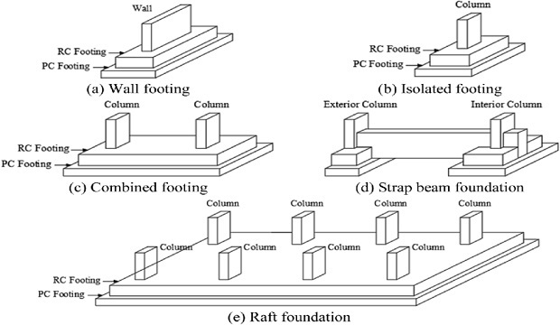
A shallow foundation usually consists of spread footings in concrete or coursed rubble masonry.
The bottom-most footing over the leveling course is of plain concrete 1:3:6 mix or of reinforced concrete of suitable thickness.
The depth of foundation should be such that the foundation rests on soil with adequate bearing capacity.
The maximum pressure on the foundation should be checked to ensure adequate factors of safety for different combinations of loads as specified in the IRC Code”.
The area around the footing due to excavation should be carefully backfilled with riprap stone and not with erodible soil.
Under what Condition we can use Pile Foundation? What are the different types of Piles according to the material?
Pile foundations may be considered appropriate for bridges in the following situations :
(a) When the founding state underlies deep standing water and soft soil ;
(b) When the foundation level is more than 30 m below the water level so that pneumatic sinking or well is difficult; (c) When suitable founding strata is available below a deep layer of soft soil; and
(d) in conditions where pile foundations are more economical than wells.
Pile foundations may be divided into two groups
(i) Foundations with friction piles, and
(ii) Foundations with point-bearing piles.
As the name suggests, a friction pile develops bearing capacity to a major extent by skin friction, i.e., it transfers the load to the adjacent soil by friction along the embedded length of the pile.
Friction piles are driven in the ground whose strength does not increase appreciably with depth.
A point-bearing pile transfers practically all of its load by end bearing to a hard stratum on which it rests.
It should be ensured that the strata beneath the bearing layer are not too weak to carry the additional loads.
The load-carrying capacity of the pile is the lesser of the values of its structural capacity and the capacity of the supporting soil to carry the load.
For an economical design, the dimensions of the pile should be so chosen that the structural capacity of the pile is nearly equal to the estimated supporting capacity of the soil for the pile.
The pile tip should be rested on hard strata having a thickness of about twelve times the diameter or side of the pile.
Since the soil conditions are generally non-uniform even at one site of a major bridge, considerable study and exercise of engineering judgment are necessary to design a proper pile foundation.
The minimum spacing of piles should be 2.5 to 3.0 times the diameter of the larger pile.
Piles can be of timber, steel, reinforced concrete or prestressed concrete.
Timber piles are not used for bridges nowadays, firstly due to lack of suitable logs of long length, and secondly susceptibility to damage by rot, borers, etc.
H-section steel piles can be used, but they are not common in India due to a shortage of steel. Reinforced concrete piles are in general use.
Prestressed concrete tubular piles of diameter 1.5 to 6.0 m have been used in the USA and Japan, in view of better ductility and high axial compressive capacity.
Concrete piles can be precast or cast-in-situ. Each type has advantages as well as disadvantages.
Since bridge structures involve foundations underwater or in soil with a high water table, precise piles are often preferred.
Precast piles can be made to high quality with respect to dimensions, reinforcement disposition and concrete strength, and hence the structural capacity of these piles can be relied upon.
However, the length of pile is limited to about 20 m depending on the driving equipment.
The main advantage of an in-situ pile is that there is no wastage of concrete and no chance of damage to the pile during driving exists.
Also, the soil occurring at the foundation’ level is seen prior to placing the concrete for the pile.
A serious disadvantage is the possibility of inadequate curing due to chemical attacks in aggressive subsoil water, which condition is likely to go undetected during construction.
Further, the occurrence of necking of concrete during removal of the forming shell and mixing of the concrete with the surrounding soil should be carefully guarded against.
How will you calculate the load carrying capacity of the pile group?
The load Carrying capacity of pile group
For point bearing piles, the safe load per pile when used in a group can be taken nearly the same as that obtained from a load test.
In the case of friction piles, the bearing capacity of an individual pile in a group of piles is less than the individual capacity under identical conditions of the soil and depth of embedment.
In other words, the efficiency of the pile in a group is less than 100 percent.
This is because most of the soil which assists in supporting a single pile by a radial distribution of the load through vertical shear will also be required to assist in the support of other piles driven nearby.
An increase in the spacing of piles will tend to improve the efficiency, but will also necessitate a larger size of the pile cap. The minimum spacing on centers is generally taken as three times the size of the pile or 1 m, whichever is greater.
The efficiency factor F, by which the bearing capacity of a single pile is to be multiplied to arrive at the capacity of a friction pile in the pile group, is frequently obtained from the Converse-Labarre formula, given by Equation
Vertical piles are generally adopted. Batter piles (also known as ranking piles) are more efficient to carry horizontal forces occurring at abutments and piers. However, batter piles are difficult to drive with accuracy on the slope.
These also need special equipment and expertise. The maximum rake permitted for precast-driven piles is 1 in 4.
When using a combination of vertical and batter piles, the analysis should consider the total system of the pile group with the pile cap, as these act together.
Types of Shallow Foundations and their Uses – Building Foundation – Civil Engineering
Explain cast-in-place concrete piles along with their advantages and disadvantages.
Cast-in-place concrete piles are constructed in their permanent position by filling with concrete the holes which have been formed in the ground in various ways for the purpose.
There are two types:
(a) the shell pile, in which a steel shell is first driven with a mandrel and concrete is placed, leaving the shell in place, and
(b) the shell-less pile, in which the pipe and mandrel used for making the hole are removed as the concrete is filled in. Reinforcement is provided for the entire length of the pile, the minimum area being 0.4 percent of the gross cross-section area of the pile.
The shell type is suitable for long piles, e.g. the Raymond cast-in-situ closed-end pipe pile 114 m long under one of the monorail piers at Walt Disney World, Florida”.
The shell-less type can be used only in firm soil or in conjunction with Bentonite slurry. Most of the methods used for cast-in-place piles are either covered by patents or specialized by particular firms.
A recent innovation is the use of rotary drilling rigs for cast-in-place piles for the flyovers at Mumbai.
Compared to the traditional percussion boring, the rotary drilling method is faster, facilitates smooth working without vibrations transmitted to the surrounding properties, permits the use of 4 mm thick liner plates instead of 6 mm plates normally required, and ensures proper anchorage at the tip of the pile.
The placing of concrete in the cast-in-place pile should be performed with utmost care. Where possible, the concrete should be placed in a clean dry hole through a funnel connected to a pipe such that the flow of concrete is directed and the end of the pipe penetrates the concrete placed just previously. Special precautions are necessary when placing concrete underwater.
When the hole is bored with the use of drilling mud (bentonite), concreting should be done after ensuring that the specific gravity of the slurry is less than 1.2.
The slurry should be maintained 1.5 m above the groundwater level if the casing is not used.
The concrete should have cement content not less than 400 kg/m and a slump of about 150 mm.
The concrete must be placed by the tremie method and must be completed in one continuous operation.
The tremie pipe, should have a minimum diameter of 150 mm for 20 aggregate. The pipe should always penetrate well into the placed concrete.
The top of the concrete in a pile should be brought above the cut-off level so that the pile will have good concrete after removal of laitance and weak concrete before pile cap is laid.
State the principles of design of a pile foundation for a Bridge Pier and sketch the detail of a typical foundation.
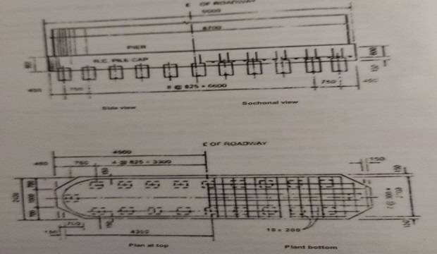
A typical pile foundation for a bridge pier is shown in Fig. 3.3, wherein sixteen precast R.C. piles have been used.
The foundation relates to a pier for a bridge with 18 m clear spans and caters to a load of 5000 kN, occurring along with a moment of 1400 kN. M at pile cap level.
The piles are of point bearing type resting on a firm stratum. The total reaction on any pile due to vertical reaction and moment is computed from Equation.
The individual piles are checked for the maximum and minimum pile reaction. Handling stresses are to be computed and checked for two cases :
(a) hoisting from the ground by one-point slinging, the slinging point being at 0.293L from the top end, and
(b) lifting by two-point slinging, the support points being located at 0.207 L from either end, L denoting the overall length of the pile.
If the pile is to function as a bearing pile, the column strength should also be investigated.
The volume of lateral ties used in the body of the pile will be about 0.4% of the gross volume of the pile.
At the two ends, the spacing will be reduced to half the normal spacing for a length of about two times the side or diameter of the pile.
A pile cap is needed to distribute the load from the pier to the piles. Normally, a thickness of about 0.9 m will be adequate.
The pile head will be stripped and the longitudinal bars embedded inside the cap for a length of about 0.6 m.
As the base of the pier covers all the pile heads, the cap need not be checked for bending and shear. However, nominal reinforcement of 18 mm diameter bars at 300 mm centers will be provided as shown in Fig.

Discuss the Well Foundation in detail along with its Basic Shapes.
Well, foundation (open caisson is the most commonly adopted foundation for major bridges in India.
This type evolved in India and has been adopted for the Taj Mahal. Since then, many major bridges across wide rivers have been founded on wells. Well, the foundation is preferable to pile foundation when the foundation has to resist large lateral forces, the river bed is prone to heavy scour, heavy floating debris are expected during floods, and when boulders are embedded in the substrate.

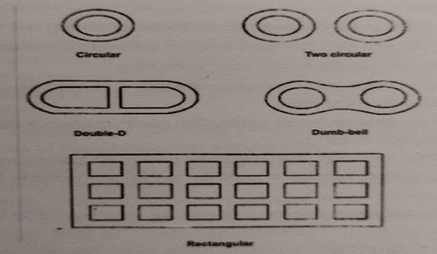
The basic shapes adopted for wells are shown in Fig. 3.4. The foundation may consist of a single large diameter well or of a group of smaller wells of circular or other shapes.
The shape of wells may be circular, double-D, square, rectangular, dumb-bell, etc.
The circular well has the merit of simplicity for construction and sinking. Double-D, rectangular and dumb-bell shapes are used when the bridge has a multi-lane carriageway.
For piers and abutments of the very large size used in cantilever, cable-stayed or suspension bridges, large rectangular wells with multiple dredge holes of square shape may be used.
The size of the dredge hole is decided so as to facilitate ease of construction and inspection of the foundation.

which material is used for constructing well steining foundation? What factors are considered An determine the thickness of the steining?
The steining is normally of reinforced concrete. The concrete used for steining should bo ME for normal exposure.
In areas of marine or adverse exposure, the concrete for steining should be at least M20 with cement content not less than 310 kg/m of concrete with a water/cement ratio, not more than 0.45.
The following factors are to be considered while determining the thickness of the steinings foundation
1. It should be possible to sink the well without excessive kentledge.
2. The wells should not get damaged during the sinking.
3. If the well develops tilts or shifts during the sinking, it should be possible to rectify the tilts and shifts without damaging the well.
4. The well should be able to resist safely the earth pressure developing during a sand blow that may occur during the sinking.
5. At any level of the steining, the stresses under all conditions of loading that may occur during sinking or during service should be within permissible limits.
Write a short note on Well Curb & Bottom and Top Plug
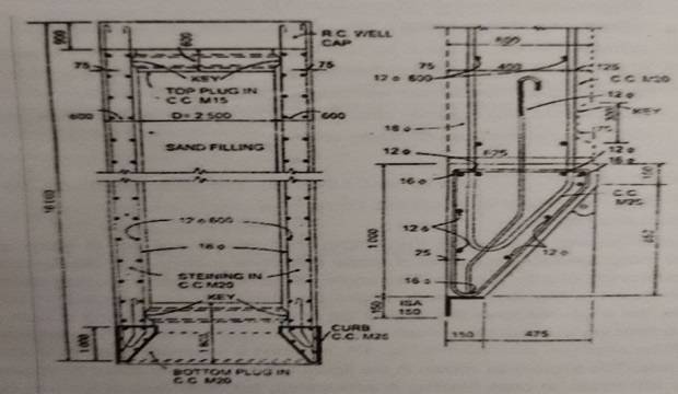
1. Well Curb. The well curb carries the cutting edge for the well and is made up of reinforced concrete using controlled concrete of grade M25. The cutting edge usually consists of a mild steel equal angle of side 150 mm.
The angle will have one side projecting downward from the curb as shown in Fig. 3.6 for soils where boulders are not expected.
In soils mixed with boulders, the angle will have the vertical leg embedded in the steining in such a manner that the horizontal leg of the angle is flush with the bottom of the curb.
The reinforcement in a well curb will be arranged as shown in Fig. 3.6, assuring a minimum quantity of steel of 72 kg/m of concrete.
The angle 0 as shown in the figure will be normally about 30 degrees and will be less for stiff strata. In case blasting is anticipated, the outer face of the well curb should be protected with 6 mm thíck steel plate for half the height of the curb and the inner face should bave 10 mm plate up to the top of the curb and 6 mm plate further up to a height of 3 m above the top of the curb.
The steel plates are to be properly anchored to the concrete. In such a case, the curb and the steining for a height of 3 m above the top of curb should have additional hoop steel.
2. Bottom Plug. Filling and Top Plug: A bottom plug is essential to transfer the load from the well steining to the base soil.
It is usually provided for a thickness of about half the diameter of the dredge hole. In practice, the bottom plug is provided up to a height of 0.3 m above the top of well curb.
The concrete used is of M20 grade, the richness of the mix being necessitated by the possibility of a loss of part of the cement due to the under-water placing of the concrete.
The concrete is usually placed in one continuous operation by the tremie method, i.e., pouring through a funnel and tube whose bottom end is kept immersed in concrete in the plastic state placed just earlier or very near the bottom at the start.
When wells are founded on bedrock, it is normal to provide anchor bars of 32 mm diameter to anchor the bottom plug into the rock by about 2.0 m depth.
A top plug of M15 concrete is generally provided for a thickness of about 0.6 m beneath the well cap and on top of the compacted sand filling.
The space inside the well between the bottom of the top plug and the top of the bottom plug is usually filled with clean sand so that the stability of the well against overturning is increased.
While this practice is good in case of wells resting on sand or rock, the desirability of sand filling for wells resting on clayey strata is doubtful, as this increases the load on the foundation and may lead to greater settlement”.
In the latter case, the sand filling is done only for the part of the well up to scour level and the remaining portion is left free.
Discuss the design procedure for a single well sunk in sandy strata.
The design procedure for a single well sunk in sandy strata by elastic theory is outlined as below. The depth of foundation is decided in such a manner as to provide adequate grip length below the maximum scour level and to rest on suitable bearing strata.
This is checked for the following two conditions of stability, namely : (i) the maximum soil reaction from the sides cannot exceed the maximum passive pressure at any depth, and (i) the soil pressure at the base should be compressive throughout and the maximum pressure should not exceed the allowable pressure o the soil at the base.
What do you mean by sinking of wells?
Well sinking is a specialized operation requiring considerable skill. When a concrete well is t0 be sunk onshore or with shallow water depth, it is usual to sink the well up to about 6 m by excavating the soil in the dredge hole by employing skilled divers, and after dredging. pumping out water from the sump to induce sinking.
A tripod and a mechanical grab operated by a power winch may also be used. The sinking of the well through the soil is resisted by skin friction along the external surface of the well and by bearing on the cutting edge at the bottom.
These resistances are overcome by the dead weight of the well steining reduced by the buoyancy of the submerged portion.
If the side friction is so great as to retard the sinking under its own weight, additional load (known as kentledge) is added at the top of the steining to aid sinking.
When the addition of kentledge practical remedy is to suspend dredging for a brief period to allow the water in the dredge hole to reach its normal level and to pump out the water under observation so that the resulting differential head reduces the average rate of sinking per day for a medium-sized well will be about 900 mm in sandy strata and about 500 mm in clayey strata.
For large-sized wells, the rate of sinking per day may be about 600 mm in sandy strata and about 400 mm in clayey strata.
For water depth less than 7 m and the stream velocity less than 2 m/s, an artificial temporary island may be built at the pier location and the curb of the caisson can be built on this island.
For depths of water 7 to 10 m and velocity in excess of 2 m/s, a cofferdam made from wooden poles, bamboo matting, and clay filling is used to protect the sand island. This method would facilitate the accurate location of the curb of the well for sinking.
Also Read This