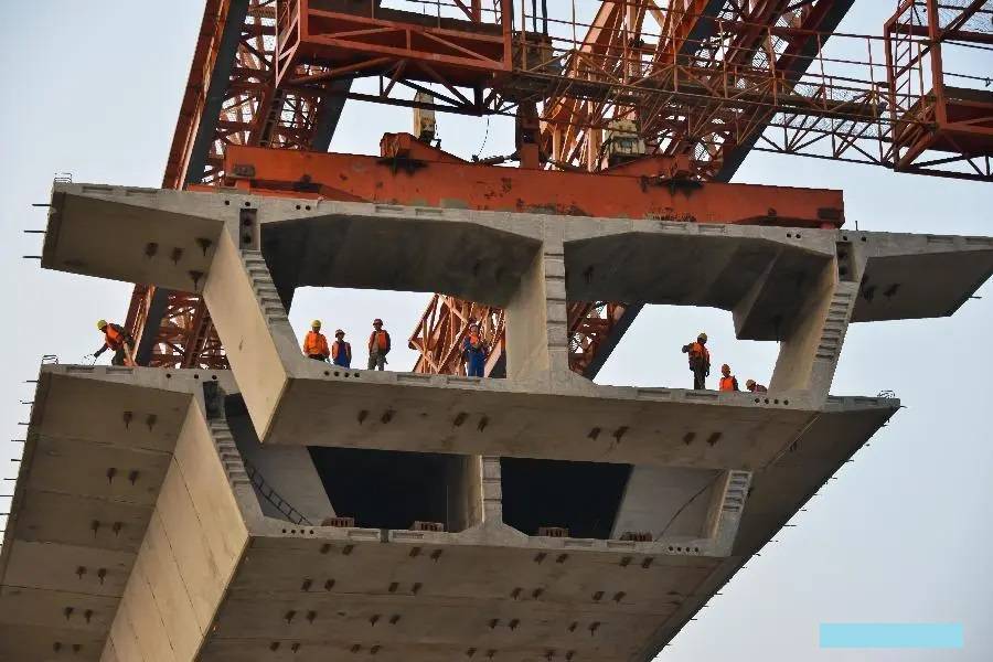
Developments in welding technology and precision gas cutting techniques in the post-second world war period facilitated the economical fabrication of monolithic structural steel forms such as steel box girders bridges characterized by the use of thin stiffened plates and the closed-form of the cross-section.
A box girder is built up using a deck plate, vertical or inclined webs, and a bottom plate.
The deck plate carries the heavy traffic loads and so needs stiff stringers and transverse beams to transfer the loads to the box webs by bending.
The box webs are subjected to bending and shear stresses.
The bottom plate acts as a chord member for bending and also gets axial tension or compression.
It should be well stiffened against buckling under axial compression.
The box girder deck can have single cells or multiple cells, the latter being uneconomical for short spans.

Typical forms of box girders are shown in Fig. and they are detailed below:
1. Rectangular box with wide cantilevering span on either side ;
2. Trapezoidal box sections;
3. Two box sections which are connected together by bracing for the integral action of the deck ;
4. One wide box section subdivided into three cells;
5. Two box sections kept wide apart; an
6. One middlebox section with one longitudinal girder on either side.
Box girder bridges have exceptional torsional rigidity resulting in better transverse load distribution.
The depth of superstructure can be shallower with this type of construction, leading to lower gradients on approaches.
The intermediate supports of such construction can be individual slender columns connected to hidden cross frames, saving substructure costs and erection time.
These girders can be conveniently used for curved and/or continuous bridges, and often provide an aesthetically pleasing solution for urban highway structures like flyovers.
Box girders are easily adaptable to composite construction, for which only narrow top flanges are needed.
For short spans, entire girders can be fabricated in the shop, enabling maximum use of shop welding.
For other cases, large portions can be shop fabricated and connected together by site splicing.
The cost of maintenance of this type of bridge is low since there are fewer vulnerable corners susceptible to corrosion. Modern steel box girder bridges invariably incorporate orthotropic plate deck and continuous spans.
Three major disasters to steel box girder bridges during construction involving the loss of 51 lives occurred during 1970-71: those at Milford Haven in the UK and at Melbourne, Australia in 1970, and at Koblenz, Germany in 1971.
These collapses were attributable more to inefficient detailing of steelwork than to incorrect design of the effective section”.
Several studies into the causes of these failures were taken up in order to clarify many aspects of box girder design and fabrication including the buckling of stiffened plates under compression, the importance of residual stresses due to welding, and the effect of initial imperfections in plates and stiffeners.
Based on these studies, stringent design requirements were evolved in Europe for this type of bridge, requiring the second-order analysis of the instability of thin plates due to geometric imperfections.
The steel box girder is generally acknowledged as an efficient, economical, and elegant form of the bridge deck.
The modern use of the box girder, however, calls for special care in design and fabrication, and erection to standards of good workmanship.
Box girders would be economical only for long spans, e.g. the Rio-Niteroi bridge across the Guanabara Bay in Brazil, with 200- 300 200 m spans. Box girder section is also appropriate if only one central girder is required to be supported on a narrow pier for functional or aesthetic considerations.
A recent innovation in connection with welded box girders is to dehumidify the interior of the box girder as corrosion protection.
Since all the stiffeners are placed in the interior of the girder, the major part of the total exposed surface area is protected from corrosion without the need for frequent painting.
The humidity inside is kept below 40%. This innovation is being applied also to the box-section decking of cable-supported bridges.
Discuss the different types of trusses used in Bridge Construction.
Truss bridges have been used economically in the span range of 100 to 200 m. A bridge truss derives its economy from its two major structural advantages :
(a) the primary forces in its are axial and
(b) with its open web construction leads to reduced self-weight when compared with solid web system The erection of a truss bridge is considerably simplified because of the relative lightness of the component members. The aesthetic appearance of a truss bridge is debatable, mainly because of the complexity of the elevation and the different directions of its members.

Types and Components
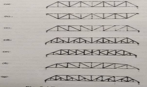
The major types of bridge trusses are shown in Fig. 2.4. The most common form is the Warren truss, shown in Fig. 2.4 (a) and (b) for the through and deck types, respectively. The Pratt truss shown in Fig, 2.4
(c) is considered to be advantageous in that the longer diagonals are in tension, while the shorter verticals are in compression.
Some of the panels towards the middle may be provided with counters if there is a possibility of reversal of stress in the diagonals.
The diagonals of the Pratt truss slope downward towards the center, whereas the diagonals of the Warren truss alternate between downward toward the center and downward away from the center.
Panels of a Warren truss may be sub-divided as in Fig. 2.4 (d) in order to provide better support for the deck, the arrangement shown referring to a through truss.
Sub-division reduces the unsupported length by half and hence leads to more slender members, especially in compression.
However, it also leads to higher unit prices of steel, less attractive final structure, and higher secondary stresses in some cases.
The K bracing system shown in Fig. 2.4 (e) is convenient when the depth or a bay is of the order twice its length. The top chords may be curved in case of longer spans, as in
What are Cable-Stayed Bridges? Give the History of it.
A cable-stayed bridge is a bridge whose deck is suspended by multiple cables that run down to the main girder from one or more towers. The cable-stayed bridge is especially suited in the span range of 200 to 900 m and thus provides a transition between the continuous box girder bridge and the stiffened suspension bridge.
It was developed in Germany in the postwar years in an effort to save steel which was then in short supply. Since then many cable-stayed bridges have been built all over the world, chiefly because they are economical over a wide range of span lengths and they are aesthetically attractive.

The wide application of the cable-stayed bridge has been greatly facilitated in recent years by the availability of high-strength steels, the adoption of orthotropic decks using advanced welding techniques, and the use of electronic computers in conjunction with rigorous structural analysis of highly indeterminate structures.
The beauty and visibility of a cable-stayed bridge at night can be enhanced by innovative lighting schemes. The early cable-stayed bridges were mainly constructed using steel for stay cables, decks,s, and towers. In some of the recent constructions, the deck and towers have been constructed in structural concrete or a combination of steel and concrete.
What are Box Girders ?” Detailed explanation
What are the different types of Cable-Stayed Bridges? Explain with the help of Diagrams.
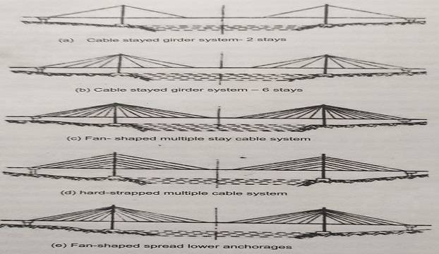
The main components of a cable-stayed bridge are (1) Inclined cables, (#) Towers (also referred as Pylons), and (i) Deck, In a simple form, the cables provided above the deck and connected to the towers would permit elimination intermediate piers facilitating a larger width for purposes of navigation, as shown in Fig, 2.5 (a).
When the number of stay cables in the main span is between 2 and 6 as in Fig. 2.5 (a and b). the spans between the stay support tend to be large (between 30 and 60 m) requiring large bending stiffness. The stay forces are large and the anchorages of cables become complicated.
The erection of such bridges involves the use of auxiliary structures. On the other hand, the use of multiple stay cables as in Fig. 2.5 (c to e) would facilitate smaller distances between points of supports (between 6 and 10 m) for the deck girders, resulting in reduced structural depth and facilitating erection by free cantilever method without auxiliary supports and enhances aerodynamic stability through increased damping capacity.
The deck can be supported by a number of cables in a fan form (meeting in a bunch at the tower) as in Fig. 2.5 (b and c) or in a harp form (joining at different levels on the tower) as in Fig. 2.5 (d). Fig. 2.5 (e) shows a typical fan-shaped cable arrangement with the anchorages at the tower distributed vertically down a certain length (modified fan form). This arrangement facilitates the easy replacement of cables at a later date in case of accidents.
The fan type configuration results in minimum axial force in deck girders. The harp form requires a larger quantity of steel for the cables, includes higher compressive axial forces in the deck, and causes bending moments in the tower. While the fan shape is superior from a structural and economical view, the harp shape possesses enhanced aesthetics.
The harp configuration cables also permit the erection of the tower and the deck to progress at the same time. Because of the damping effect of inclined cables of varying lengths, the cable-stayed decks are less prone to wind-induced oscillations than suspension bridges.
Based on the span arrangement, the cable-stayed bridge can be one of four types : (a) Bridge with an eccentric tower, e.g. Hoescht bridge on Main River ; (b) Symmetrical two-span bridge, e.g. Otmarshein bridge in France ; (c) Three-span bridge, e.g. Brotonne bridge, France; and (iv) Multi-span bridge, e.g. Millau viaduct, France. The multiple stay cable system also permits easy replacement of cables if needed
How the Cables are arranged in Cable-Stayed Bridge.
The cables may be arranged in one central plane (axial suspension) as in Norderelbe bridge, in two vertical planes with the twin-leg tower as in Stromsund or Dusseldorf North bridges, or in two inclined planes as in Severin’s bridge” (lateral suspension).
The single-plane system has the advantage that the anchorage at deck level can be accommodated in the traffic median resulting in the least value of the required total width of the deck. With the two-plane system, additional widths are needed to accommodate the towers and deck anchorages.
Aesthetically, the single-plane system is more attractive as this affords an unobstructed view on one side for the motorist. Other notable examples of single-plane systems are the Rama IX bridge (1987) in Bangkok, Thailand, the Sunshine Skyway bridge (1987) in Florida, USA, and the Normandie bridge (1994) in Frane.
In the case of a two-plane system of cables, a side view of the bridge would give the impression of the intersection of the cables. The choice of the cable arrangement should be done with care and diligence, so as to ensure an enhanced aesthetic quality of the bridge through a system in harmony with the environment.
The two inclined plane system of cables with the cables radiating from the apex of an A-frame as in Severin’s bridge facilitates the three-dimensional structural performance of the superstructure and reduces the torsional oscillations of the deck due to wind, thus enhancing the aerodynamic stability of the bridge.
The torque due to eccentric concentrated loads would necessitate the use of a box section orthotropic deck for the single-plane system. The decking is generally of orthotropic plate system with box girders for the two-plane system also but can be of prestressed concrete girders as in Maracaibo bridge in Venezuela and Hoescht bridge over the Main river in Germany.
The Rama VIII bridge in Bangkok uses a combination of two-plane and single plane systems. Using an inverted-Y pylon, the 300 m main spans is supported with twin inclined stays while the back span has a single plane system of stays.
Also, Read This