The Contour survey procedure leveling is the art of determining and representing the relative heights or elevations of different points on the surface of the earth, Continuous surveying, and leveling are two important aspects of civil engineering.
The elevations and depressions of the ground surface can be shown on a map with contour lines. A contour survey procedure may be defined as the line of intersection of a level surface with the surface of the ground.
With the help of leveling and contour survey procedure, it is possible to obtain the levels of roads, building plinth levels, parking, and drainage line levels, etc. With the help of a contour survey, we can obtain accurate outlines of the surface of the ground.
Considering the importance of these aspects, every engineer should have sufficient knowledge of handling the instruments required for contour survey and leveling.

USE OF CONTOUR SURVEY PROCEDURE
1. TEMPORARY BENCHMARK (T.B.M.)
2. LINE OF COLLIMATION
3. BACKSIGHT (B.S.)
4. FORESIGHT (F.S.)
5. INTERMEDIATE SIGHT (I.S.)
6. CHANGE POINT (C.P.)
7. HEIGHT OF INSTRUMENT (H.I.)

8. INSTRUMENTS USED FOR LEVELLING
9. OTHER MATERIALS REQUIRED FOR THE WORK
10. HOW TO REMOVE THE INSTRUMENT FROM THE BOX
Before removing the instrument from the box, mark the positions of
- Object glass
- Eye-piece
- Clamp
- Tangent Screws
So that it can be placed in the box in its proper position without any difficulty.
CONTOUR SURVEY – Field to Paper to 2D to 3D
SETTING UP THE DUMPY LEVEL
Release the clamp screw of the instrument, hold the instrument in the right hand, and fix it on the tripod by rotating only the lower part with the left hand. Tighten the screws of the instrument firmly.

2. LEG ADJUSTMENT
- Place the instrument in the desired position at a convenient height.
- A tripod should be leveled by leg adjustment.
- The legs of the tripod should be spread about 1.1 meters (3’6″).
- The points of the tripod legs should be firmly placed.
- If the extension legs are to be used, they should be checked to make sure that all the nuts are properly tightened.
- Bring all the foot screws in the center of their run.
- Fix any two legs firmly into the ground by pressing them with the hand and move the third leg to the right-left until the main bubble is approximately in the center.
- Then move it, inward outward, until the bubble of cross-level is approximately in the center.
- Finally, the tripod leg should be fixed in a position where both the bubbles are approximately in the center of their run.
- If leveling is done by means of the tripod legs, it helps save time.
3.LEVELLING UP
- Place the telescope parallel to a pair of foot screws and bring the bubble to the center of its run by turning these screws equally either both inward or outward.
- Turn the telescope through 90 degrees, so that it lies over the third toot screw and center the bubble by turning this screw.
- Bring the telescope back to its original position without reversing the eye-piece and object glass end.
- Again bring the bubble to the center of its run and repeat these operations until the bubble remains in the center in both positions, which are at a right angle to each other.
4. FOCUSSING THE EYE-PIECE
- Remove the lid from the object glass and hold a sheet of white paper in front of it.
- Move the eyepiece in and out until the crosshairs are distinctly seen.
5. FOCUSSING THE OBJECT GLASS
- Direct the telescope towards the staff. Looking through the eye-piece, bring the image of the staff between the two vertical hair of the diaphragm, by lightly tapping the telescope. Adjust the object by turning the focussing screw until the parallax is completely eliminated.
- Take the reading.
- NOW YOUR DUMPY LEVEL IS READY FOR WORK
6. HOLDING OF THE STAFF
The staff should be held truly vertical. While the reading is being taken, guide the person holding the staff for the right-left direction movement, to set the staff perfectly vertical, then take the reading. perfect staff reading.

WORKING OUT THE REDUCED LEVELS
There are two methods of working out the reduced levels of points from the staff readings taken in the field.
- The collimation or instrument height method
- The rise and fall method
- The first method, i.e. collimation height method is less tedious, more rapid, and involves less calculations, as explained below.
- The collimation method consists of finding the elevation of the plane of collimation (H.I.) for every set up of the instrument and then obtaining the reduced levels of points with reference to the plane of collimation.
- To begin with, determine the elevation of the plane of collimation for the first set up of the level by adding the backsight to the reduced level of the benchmark.
- Then calculate the reduced levels of the intermediate points and the first change point, by subtracting the staff readings were taken on these points (i.e. 1.S. and F.S.) from the elevation of the plane of collimation (H.I.).
- Now, when the instrument is shifted to the second position, a new plane of collimation is set up. The levels of the two planes of collimation are correlated by means of the backsight and foresight taken on the change point.
- Now, work out the reduced levels of the successive points and the second change point, by subtracting their staff readings from the elevation of this new plane of collimation.
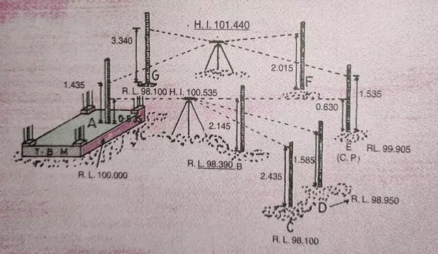
- Let us consider an example.
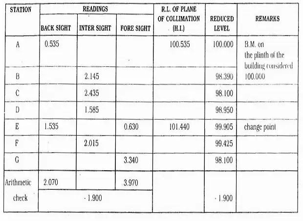
After taking the readings, as shown in the table above, calculate the reduced levels of different staff stations as explained below.
R.L. of station D = 100.535 – 1.585 = 98.950
R.L. of station E = 100.535 0.630 = 99.905
So, now calculate the R.L. of other stations.
R.L. of station F = 101.440 – 2.015 = 99.425
R.L. of station G = 101.440 3.340 = 98.100
To check the leveling work, take the reading on
B.M. ‘A’ and calculate the R.L. It should be 100.00 If the error exceeds the permissible limits, the work must be repeated.
Arithmetical check: The difference between the sum of the backsights and the sum of the foresight should be equal to the difference between the first and last reduced levels. This check verifies the calculation of the reduced levels of the planes of collimation and of the change points.
- Sum of the backsights: 2.070
- Sum of the foresight: 3.970
- Difference = = – 1.900
- First R. L. = 100.00
- Last R. L. = 98.100
 |
| reduce the level by collimation method |
CONTOUR SURVEY PROCEDURE
1. INTRODUCTION
- The elevations and depressions (undulations) of the ground surface are shown on a map by means of contour lines.
- The line joining the points on the same level on a map is called a contour line or a contour.
2. CHARACTERISTICS OF CONTOUR LINES
- Contour lines run close together near the top of the hill, indicating very steep ground.
- A uniform slope is indicated when contour lines are uniformly placed.
- A plane surface is straight and equally placed.
- A ridgeline is shown when higher values are inside the bend in the contour.
- For a valley line, lower values are inside a bend or a loop.
- Contour lines cannot cross each other or merge on the map.
- Contour lines cannot end anywhere.
3. PROCEDURE OF CONTOUR SURVEY
- Make the points of equal intervals. e.g., 7 to 10 meters depending on the slopes of the ground.
- These points can be marked initially with the help of a ranging rod.
- Fix up one parallel line to the boundary of the plot with the help of ranging rods. Bisect the ranging rod from one end and mark all the intermediate points at equal intervals on the ground by lime powder.
- Put one right angle line to this line and mark equal interval points by lime powder on the ground.
- By taking parallel lines to these two lines complete the traverse.
- Note down any sudden drops, well position, sudden ramps, heaps, etc. by taking additional reading between the grid points.
- Hold the staff vertical while taking the readings.
- Calculate the R.L. of each point with reference to T.B.M. taken on a permanent structure.
- Plot a grid of equal intervals, on a map of the plot, stating boundaries.
- Write down the R.L. at each junction of horizontal and vertical grid lines.
- Join the contour lines of equal R.L.s and write down the value of the contour line outside the plot boundary at both ends of the contour line.
- Contour lines are drawn as fine smooth freehand curved lines of inform width. French curves should be used as far as possible.
4. USE OF CONTOUR MAP
- The contour survey procedure should be carried out before starting any project work.
- On a contour map, the layout of all the buildings of the project are plotted.
- Plinth parking levels of the buildings, and road levels, considering all stormwater aspects, drainage levels, etc. are decided with respect to all the plot levels with the help of a contour map.
- Insist that the Architect plumbing consultant and all other consultants should write R.L.s of each structure.
- To know the overall topography of land or plot.
- To decide the parking plinth levels of each building.
- To decide all internal roads levels.
- To decide and design complete the drainage system for the entire project, considering natural slopes of the ground, invert levels of nearby Nalla, drainage chamber, etc. with minimum excavation and therefore. minimum cost.
- To reduce the cost of excavation and filling for roads plinths etc. consider cutting, and filling quantities at the initial stages while planning and designing the building.
- To decide the levels of all development works such as garden swimming pools, recreation facilities, septic tanks, underground water tanks, etc.
- While leveling, always hold the staff vertically.
- Always make arrangements for covering the instrument if it rains.
- Handle the instruments carefully. Do not overtighten any screws.
- Enter all the readings taken as per the standard format and preferably in the field book.
- During the contour survey procedure of a plot, take the readings of adjacent plot areas for at least one-two grid.
- To avoid any disturbance to the setting of the instrument, do not allow children others near the instrument.
IF YOU LIKE THIS POST CONTOUR SURVEY PROCEDURE – USES, METHODS, MAPS LIKE THIS GETTING GOOD INFORMATION SO PLEASE SHARE THIS POST-SOCIAL NETWORK EXAMPLE FACEBOOK, TWITTER SOCIAL MEDIA SITES SHARE IT

useful for me